hole calc #

Hole calc is a simple web application that allows you to calculate the diameter of a bore from the size of three cylindrical pin gages that fit into it, using Descartes’ Theorem. This functionality is useful for machinists and anyone else who needs a semi-precision method of measuring bore diameters without dedicated tools. Try it out here. Read the guide for more usage details and see the github repository for source code.
Background #
Hole calc was developed after a discussion on a machining forum about using three gage pins as an ad-hoc method of measuring a bore diameter. While a couple people had made simple spreadsheets for doing this calculation, there was no readily available online calculator. At the time, I had used python and flask to build a couple of simple in-house utilities for my day job, so I decided to build hole calc to fit this niche. There are a huge number of general purpose “machinists calculators” online, so my intention was to narrowly focus on this particular measuring method and develop an extremely simple, intuitive and informative way to perform this kind of measurement.
Bore measuring methodology #
Below is a brief description of the bore measuring method hole calc is designed to enable. I refer to this procedure as the “three gage method” for bore measuring, I’m unaware of a more concise or standardized name.
- Prepare the hole to be measured. Make sure the bore interior is clean and dry and the edge of the hole is free from burrs.
- Select three clean, dry gage pins that will slide in to the bore together.
- If needed, replace one of the pins with a larger or smaller diameter pin in order to adjust the fit within the bore. The pins should slide in and out by hand. Each pin should contact both the other two pins and the wall of the bore without any play.
- Once a well fitting combination of pins is found, enter the diameter of each pin into the three pin calculator.
- If you want to see a result range based on gage class, select the “Tolerance” radio button. Enter the tolerance class and sign for each gage pin using the drop-down fields that appear. See the “Precautions” selection below for more information on tolerance mode.
- Select desired units and digits of precision from the drop-down fields.
- Press the “Calculate” button
- Your result should appear to the right of the input fields (desktop) or below (mobile). If your inputted values are invalid (not a number or mathematically impossible), an error message will appear.
While this method works to measure an unknown bore diameter, we can also use the reverse mode of hole calc to determine the diameter of the third pin, given a known bore diameter and two pin diameters. This gives the used a way to make up combinations of pins that act as “GO/NOGO” gages for a given diameters.
Effects of tolerance stack-up #
All gage pins have a class indicating the tolerance of the pin diameter and are designated as plus or minus relative to the nominal size. The tolerance of each pin and resulting stack-up will affect the measurement of the hole. Hole calc has a “Tolerance” mode that will automatically calculate minimum/maximum values based on tolerance class and sign of each pin. While this can provide a high degree of numeric precision, the degree to which this reflects the actual size of the hole will depend on the precision of your measuring process. The tolerance ranges for each pin size and class are based on specifications provided by ASME B89.1.5-1998. ASME B89.1.5-1998 only defines tolerance classes for gages from 0.0010 in to 21.010 in (0.254 mm to 533.65 mm), so values above or below those limits will generate an error.
The third mode provided by hole calc is a pin gage diameter calculator. This tells you the allowable diameter range for a gage pin of a given nominal diameter, tolerance class/sign, and units of measure. As I already had to incorporate this data for tolerance mode, it was easy to implement this calculator as an afterthought. This functionality is duplicated by many other gage diameter calculators online, there’s nothing particularly special about hole calc’s implementation. Suprisingly, when doing research for this calculator I found that the values provided by several other gage diameter calculators differed slightly from each other and from the published ASME spec. I was unable to determine the cause- perhaps references to old versions of the spec or misprints in secondary sources? After seeing these inconsistencies in online sources, I ended up purchasing the spec directly from ASME for reference in this project.
Other factors affecting precision #
It is fundamental principle of all machining tasks that the methods of both material removal and measuring should be matched to the required degree of precision. While we can quantitatively characterize the tolerance stackup of the three gage pins used in this measuring method, there are other mechanical factors that affect the precision of the result.
The three gage method assumes the bore to be perfectly round. If the bore is oval-shaped or lobed, this method will provide inconsistent results depending on the relative position of the gages within the bore. This loss of precision should be taken into account when measuring products of operations where lobed holes are likely, such as drilling. Therefore, the three gage method is best suited to measuring holes produced by operations which do not typically produce lobed holes (such as boring).
There are other factors that affect the precision of this method, even when assuming a round hole. As with the standard GO/NOGO method of measuring a bore, insertion pressure, surface roughness, hardness, cleanliness, (lack of) edge breaks and material will all affect how easily gages slide into the bore and therefore the choice of gages used for the final measurement. Since the three gage method has three separate pins entering the hole at once, as opposed to the single pin used in the GO/NOGO method, these factors are compounded. While it’s difficult to quantitatively determine the loss of precision, we can state that the three gage method will always have less precision than measurements performed with GO/NOGO pins of an equivalent tolerance class.
Technical details #
The hole calc application is built with the Flask web application microframework. Flask-WTForms was used to build the calculator input forms. The source code for the flask app is contained in main.py, while Flask templates reside in the templates subdirectory. The holecalc directory contains the python module responsible for all the math.
Hole calc is styled using Pure.css. The display font used for the menu and headings is Space Grotesk by Florian Karsten. The color scheme may be viewed here.
I deploy hole calc as a Docker container, using tiangolo/meinheld-gunicorn-flask-docker as the base image. It’s hosted through DigitalOcean’s App Platform. App platform has been quick to setup and trouble-free, although more economical hosting alternatives probably exist.
Math #
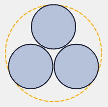
Hole calc relies on the fact that three round pins closely fitting in a round bore will be tangent to both each other and the bore itself. This satisfies the conditions of Descartes Circle Theorem. The geometric relationships of all four circles (a.k.a. the Soddy circles) has been well characterized over the years, so we can deterministically calculate the size and relative arrangement of the circles.
I’m not a mathematician and rarely encounter the advanced geometry used for these calculations in my work or other interests. While the implementation of the calculator software was generally straightforward, figuring out some of the math equations was challenging. My first priority was to implement calculation of bore diameters for the three pin calculator and calculation of the missing pin for the two-pin/reverse calculator. These were straightforward uses of Descartes Theorem, well described on the internet even to someone like me with very rusty math skills.
After sharing my MVP version of the calculator and receiving feedback from users, it quickly became evident that I should actually draw the relative diameters of the pins within the bore. There were many non-intuitive solutions provided by the calculator that were difficult for users to believe without graphical representation. For example, running the three-pin calculator with pin values of 0.5", 0.1" and 0.2", which calculates to a diameter of 1.125". While this solution is mathematically valid, users may have trouble visualizing the pin configuration in the bore, which undermined the credibility of the calculator even in more conventional pin configurations.
This sent me down the path of determining how to plot the relative center positions of each circle. This task turned out to be more difficult than the circle size calculations. I ended up combing through old academic websites, reddit and stack exchange posts and even Forum Geometricum papers. I spent a slightly embarassing amount of time going through this 2007 paper by Nikolaos Dergiades trying to extract a usable formula. Ultimately my lack of familiarity with high level geometry made this approach unproductive. I considered reaching out to an academic or math student for help, but I couldn’t think of anyone I was comfortable asking.
Since I wasn’t willing to take advanced geometry classes for the sake of this project, I decided to change my approach. My next step was to find open source code implementations of related problems that I could learn from. The four mutually tangent circles are a special case of the Problem of Apollonius. This special case is related to the construction of an Apollonian gasket, a common, visually appealing type of fractal. There are tons of software toys that implement the task of generating cool fractals, so there were many open source programs I could look to for inspiration. I ended up finding Ludger Sandig’s apollon, which is a small set of python scripts for calculating and rendering Apollonian gaskets. Sandig’s implementation was the biggest inspiration for how I eventually programmed the circle-drawing functionality in hole calc.